![]()
|
© 2021 Drake Smith - Please do not use or reproduce this elsewhere. Feel free to link to it though. Install Electronic Cruise Control on a K75/K100 Rostra 250-1223 Now newer and improveder for 2021!
2021 Cheat Sheet V2.0: The link below is a one page summary of how to set up the switches and wire the Rostra 250-1223 on a K bike. I recommend that you read this entire web page and then use this in the garage as a guide for the installation. Rostra.250-1223.K.Bike.Cheat.Sheet.V2.0.pdf Manufacturer Disclaimer: This documents what I did in the hope that others might find it useful. Rostra specifically states that they DO NOT condone the use of their cruise control products on motorcycles. Therefore they will not provide installation support if they know that you are installing one of their cruise controls units on a motorcycle. My Disclaimer: You are modifying the throttle control on a vehicle that is dangerous enough in the first place. Therefore, if you do this then you do so at your own risk and I am not liable for anything that happens as a result of your reading this.
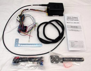
Note: For K1s, K100RS4Vs and K1100s the wiring will be the same but you'll probably need to figure out a different way to hook it up to the throttle linkage since the throttle bodies are different than on a K75/K100. I think the way I did it for my Audiovox CCS-100 installs would work well. Caution: It's a good idea to disconnect the ground from your battery before performing any electrical work on your K bike. The Cruise Control Unit In the past I've installed something like fifteen or so of the Audiovox CCS-100 vacuum cruise control units on various K bikes with excellent results. However, Audiovox stopped making them several years ago and there's still high demand so they usually sell for $250ish on Ebay these days. The Murph's Kits site used to sell exact replicas of the CCS-100 but that is no longer the case. Back in 2013 I did my fist install of the 1223 electronic cruise control on a turbo'd 1986 K75. They sell for $230 on Amazon these days. In early 2021 I purchased a 1995 K75 and decided to install another 1223. Based on my 2021 install I have added updated this page with my improvements and more pictures. Here's the Rostra installation and owner's manual: Rostra.250-1223.Manual.RevG.2012.pdf Control Switch On my first few CCS-100 installs, I used the control switch that came with it and mounted that above the choke lever. Like so:
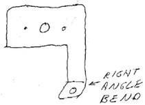
Using 1/8" thick aluminum sheet I fabricated a flag shaped bracket to mount it on the clutch perch. It looks like this from behind:
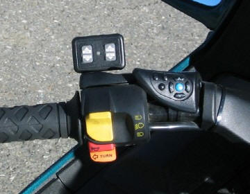
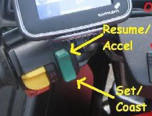
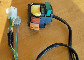
Even though I'd filled the control switches with RTV to "waterproof" them, eventually one of them leaked, shorted and failed. Then I came up with the idea of using windscreen up/down switch from a K1100LT to control the cruise control. This has several advantages. First, it actually IS waterproof since it was designed motorcycle use. Next, it's an OEM switch so it looks like it belongs there, unlike the aftermarket look of the Audiovox or Rostra switch. Finally, it's ergonomically more convenient to use. You control it using your left thumb without having to remove your hand from the grip.
The up button of the windscreen switch functions as the Resume/Accel/"Tap-up" button and the down button functions as the Set/Coast/"Tap-down" button. "Tap-up" and "Tap-down" allow you to fine tune your cruising speed once the cruise control is engaged.
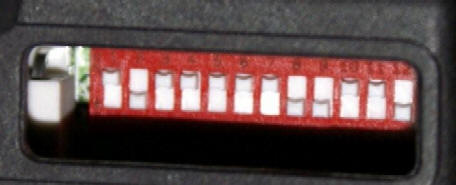
Control Unit Switch Settings DIP Switches As a universal cruise control, the 1223 has a set of 12 binary switches which allow you to configure the operation to your particular vehicle and type of installation. These are located under the rectangular rubber cap on the 1223 control unit. You may want to set the initial switch settings ahead of time on the workbench. Up is on, down is off.
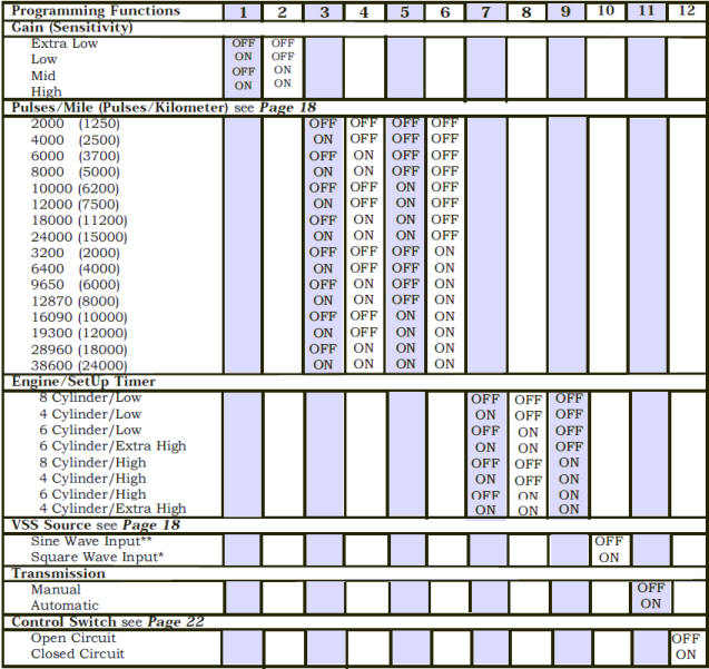
The following table from the Rostra manual shows how the unit should be programmed by setting these switches. Note that if you want to experiment with different switch settings you will need to turn the motorcycle on and off in order to reboot the 1223.
Note: The following are the switch settings that seem to work best on a lightly loaded standard K75. For different K models with more power and/or heavier loading you may need to experiment in order to fine tune the switch settings. Switches 1 & 2 - Gain (Pull Strength): These switches determine how hard the 1223 pulls on the throttle when it kicks in. Set these to OFF-OFF. (Extra Low) Switches 3-6 - Pulses/Mile: These are to set the pulses/mile received from the speedometer sensor. A K bike speedometer sensor puts out a little under 5,000 pulses/mile so I set these to ON-OFF-OFF-OFF.(4,000) If you set these to OFF-ON-OFF-OFF (6,000) then the "tap-up" fine tuning of the set speed will be slightly larger and the 1223 minimum speed will be slightly lower. On my K75 set to 4,000 the 1223 minimum speed is about 27-28 MPH. Switches 7-9 - Engine/Setup Timer (Pull Speed): Here are the possible 7-9 settings:
According to the Rostra website, these switches determine how "fast" the control unit pulls on the throttle cable. It's not really clear from either Rostra's manual or website but I believe that this is the correct sort order for these settings. If it pulls too quickly then you will have a jerky ride. If it doesn't pull quickly enough then the cruise won't be able to accelerate enough to maintain the set speed when you're going up a hill. Low in the table refers to low weight to high horsepower ratio. Start with the lowest setting, OFF-OFF-OFF, and work your way down the table to fine-tune things. What seems to work best on a K75 is ON-OFF-OFF. (4 Cylinder Low) Switch 10 - VSS Source: The speedometer sensor on a K bike is an analog inductive device that generates a sine wav. Set this to OFF. Switch 11 - Transmission: Set this to OFF for a manual transmission. Switch 12 - Control Switch: Set this to OFF if you're using the BMW windscreen switch or another normally open switch. Summary: Here's how the switches are set on my K75:
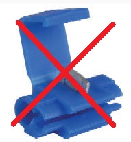
Electrical & Wiring Preface - Tapping Into Wires: The 1223 kit comes with several Scotchlok connectors for tapping into existing wires. I've found these to be unreliable and sometimes they will cut through the wire you're tapping into. I much prefer to use Posi-Taps for tapping into wires.
Power Relay Since the 1223 uses electrical power to pull on the throttle it uses a fair amount of power so a fused switched power supply is needed. Using standard Bosch terminal designations, here's how to wire the relay:
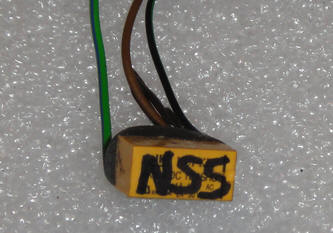
1223 Wiring Red Wire: According to the installation instructions you're supposed to hook this up via a cruise control on/off switch to the "hot" brake switch wire (green/black on a K bike rear brake switch) but that wire is just switched power so I run that to the relay output power above to simplify things. And I don't see the need for a cruise control on/off switch as I prefer that the cruise control come on automatically when the bike is switched on. I connect this wire to my cruise control power relay. Brown Wire: This is the main 12V+ power to the 1223. I connect this wire to my cruise control power relay. (This wire was actually dark gray on one of the 1223s that I installed. See wiring addendum at the bottom of this page.) Black Wire: This is the main ground for the 1223. I've read that the 1223 can be sensitive to poor grounding so I connected it to the negative terminal of the bike's battery using a ring terminal. Violet Wire: When the brake light goes on, this wire senses 12V+ and disengages the 1223. You can tap this into the (gray/yellow) brake light wire. Since I have an LED brake light, I added a normally closed PCB relay that grounds the violet wire when the brake light is not lit.
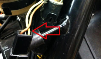
If you want to use a standard relay for this then refer to the cheat sheet linked to at the top of this page. Light Gray Wire (VSS): This wire monitors the pulses from the speedometer sensor so the 1223 knows to speed up or slow down in order to keep you at your set speed. Tap that into the yellow speedometer sensor wire under the right side battery cover.
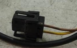
Later K bikes have a slightly different connector but the wire colors are the same - yellow & brown.
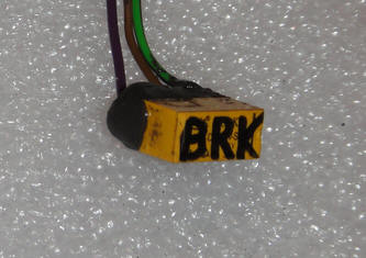
Light Green Wire: (Optional if you tap the blue wire into the coil.) This is the Neutral Safety Switch wire. It disengages to keep the 1223 from over-revving if you pull in the clutch or the bike is in neutral. The 1223 disengages when this wire is grounded. Since K bikes use the clutch switch to put 12V+ to the start button when the clutch is pulled in, I used a normally open PCB relay to send a ground signal to the 1223 when the clutch is pulled in or the bike is in neutral. Tap the positive trigger wire for the relay into one of the black/green wires (power to the start button) at the connector for the right combination switch.
If you want to use a standard relay for this then refer to the cheat sheet linked to at the top of this page. Blue Wire: As a safety feature, this wire monitors the RPMs at the ignition coils to keep the 1223 from going into run-away mode and over-revving the engine. However, since I'm using the clutch switch this wire does not need to be wired to the coils. Per the installation instructions that came with the 1223, I grounded this wire to the negative battery terminal with the main ground wire (black wire above) to avoid it introducing "trashy" signals into the system. Dark Green Wire (DOWN): This is the wire for the Set/Coast/"Tap-down" button. Connect that to the blue (down) wire of the windscreen switch. Yellow Wire (UP): This is the wire for the Resume/Accel/"Tap-up" button. Connect that to the gray (up) wire of the windscreen switch. Green Wire of the BMW Windscreen Switch: This provides switched 12V+ power to the windscreen switch. Tap that into the green/black wire of the black special equipment connector in the relay box or the output (87) from the power relay described above. Orange Wire: (Optional) This wire puts out a ground signal for an indicator lamp when the cruise control is engaged. For the 86 non-ABS K75 I wired that up to an amber led I installed in the unused indicator next to the low fuel light in the instrument cluster. For the 95 ABS K75 I installed a green LED in the choke indicator and tapped it into choke indicator's violet/white wire that can be found under the gas tank on the left side. Even though 1991 and later K75s and K100s don't have the choke light switch from the factory the violet/white is still there under the tank and will work.
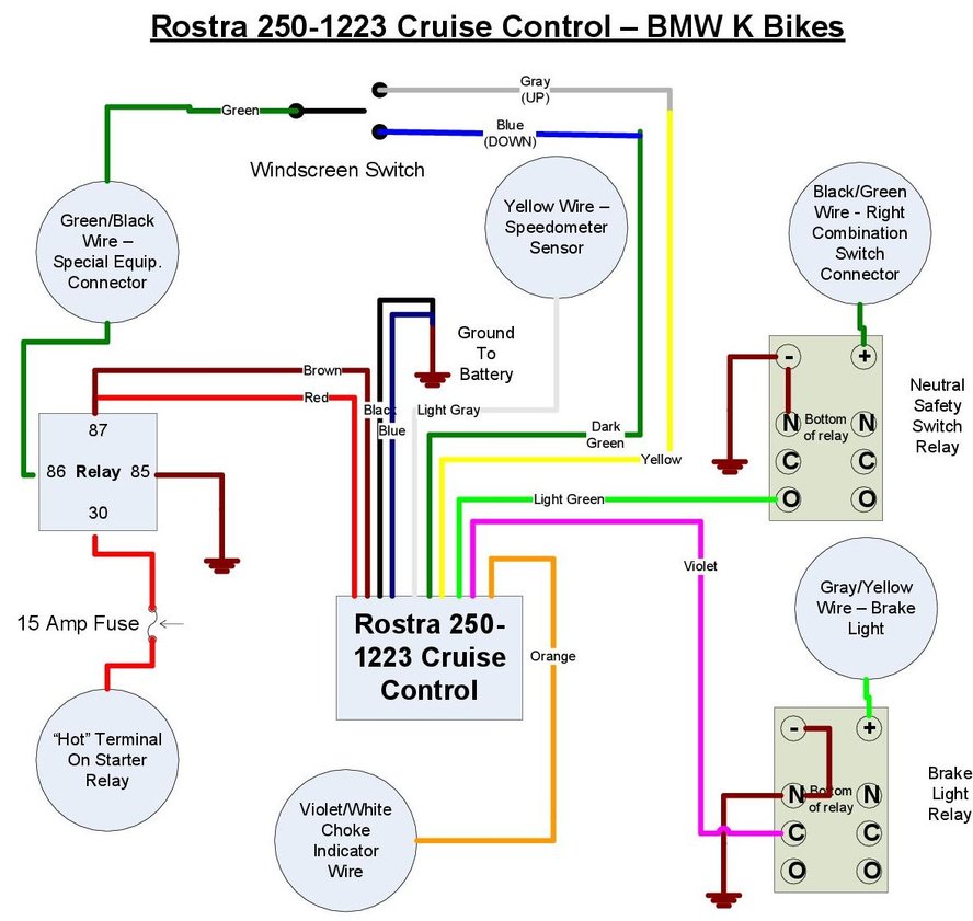
Click on the wiring diagram below to have a larger version open in a new tab for printing:
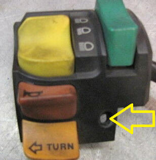
K1100LT Windscreen Switch The housing of the K1100LT left combination switch is the same as a K75/K100 so it will "bolt right up" to a K75/K100 choke perch. There's a Phillips screw at the bottom middle of the face of combination switch that holds the combination switch on. If that hasn't been removed since your bike left the factory then there can be some corrosion in the threads so be sure to use a good screwdriver and lots of pressure to avoid stripping the head of it.
For the headlight, horn and turn signal, the K1, K100RS4V and K1100 models use a different combination switch wiring harness connectors than K75s/K100s. Therefore, you'll need to graft the connector from your old left combination switch to the K1100LT combination switch with a windscreen switch. However, both use the same wire colors so it's a straightforward task.
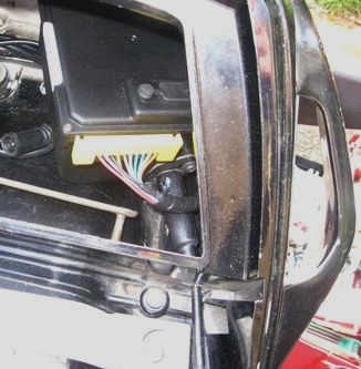
Hardware Installation 1223 Control Unit: I chose to install the 1223 in the tail cowl of my K75. I drilled a hole in the lower left hand corner of the tail cowl for the cable to pass through. I removed the tail cowl from the bike to drill this hole.
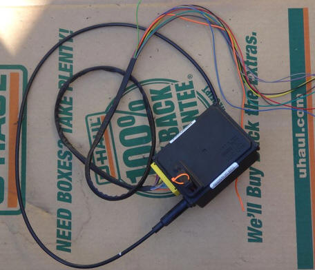
K75/K100 ABS Control Unit Mounting: The Rostra control unit is rather bulky and would make using the K75/K100 ABS control unit bracket impossible so I just left the ABS control unit loose in the tail cowl. It's actually a pretty tight squeeze with both the Rostra and ABS brain loose in the tail cowl so they don't bounce around. Routing The Wiring: After soldering some longer wires to the orange wire (indicator light ground) and light green wire (neutral safety wire that grounds when the clutch is pulled in), I clumped all ten wires together in about 2 1/2 feet of 8mm (5/16") heat shrink tubing. Ten wires is a lot to pull through that small tubing so you might want to use a 9 or 10mm tubing to make life easier. (Note that there's no need to actually shrink the tubing. It's just there as a casing.)
I run this out of the left turn signal wiring hole in the lower left corner of the tail cowl and then zip-tie the bundle to the left frame rail under the tail cowl, similar to how the factory tail light wiring runs along the right frame rail. Then up near the battery I split off the various wires to where they need to go.
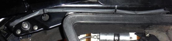
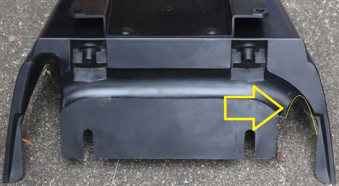
In order for the rear fender to fit well on the right rear corner of the frame, cut a U for the wiring bundle here:
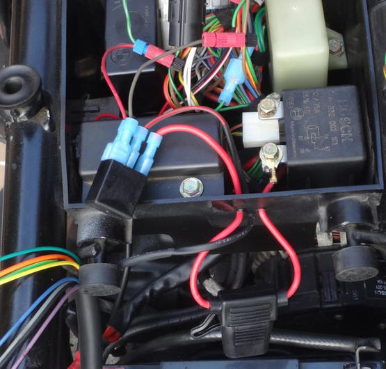
Wiring Installation In order to not have a bunch of wires running all over, next to where the L-Jetronic lives I split up the wiring and route it in three sub-clumps.
Left sub-clump: This contains all of the wires that go up under the tank and continues along the left side frame rail:
Right sub-clump: To the right side of the bike
Middle sub-clump: To switched power relay in relay box
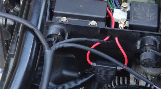
I drilled a few holes in the back of the relay box for the power wires. As you can see I installed a 15 amp in-line fuse outside of the relay box for somewhat easy access. The power input to the switched power relay goes through the fuse from the "always on" unswitched rear terminal of the starter relay. The trigger for the power relay (86) is tapped into the green/black wire of the special equipment connector from Fuse 1.
Windscreen Switch Power Wire: Run a wire from the green wire of the windscreen switch connector back to the green/black wire (Fuse 1 switched power) of the black special equipment connector in the relay box.
Throttle Connection
2013 Throttle Connection The throttle connection on my 2013 install worked OK but I decided to do a better job this time with less slack and a more direct connection angle. 2021 Throttle Connection: In order to get the throttle connection closer to the air plenum I trimmed the plastic snap-in adapter.
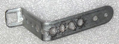
In 2013 I bent everything at right angles as shown below and wasn't to picky about where I made the bends:
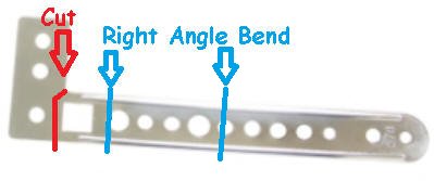
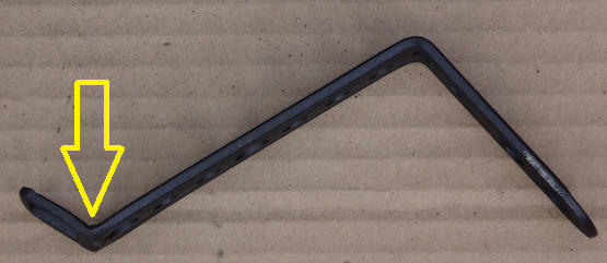
. In 2021 I was more careful how I did the bends so that the end of the 1223 throttle cable would be closer and more directly pointed at the throttle connection point and then painted it black:
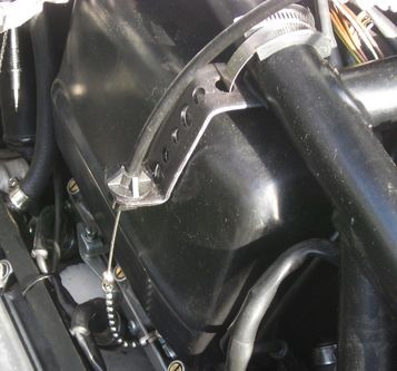
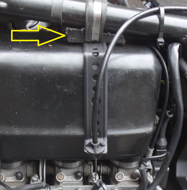
I inserted a piece of HDPE between the frame and the bracket to push it down onto the plenum.
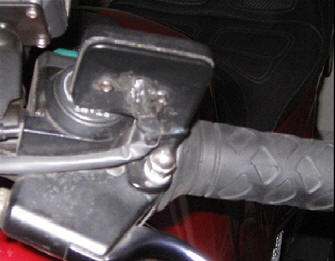
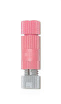
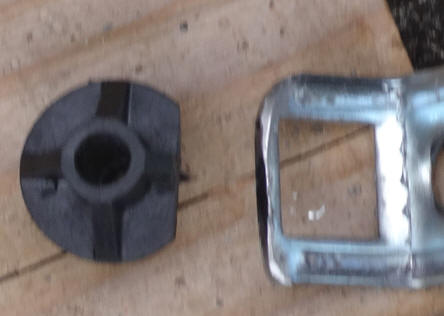
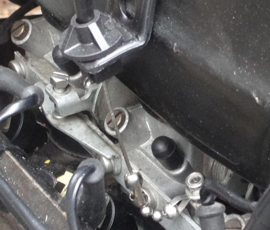
I use the connector from the kit shown below to attach the beaded chain to the throttle body adjustment screw with blue paint on it.
I attach it with a nylock nut to the factory throttle body adjustment screw between the #2 and #3 throttle bodies. DO NOT mess with the adjustment screw with blue paint on it as it should remain where the factory set it. I just put a connector and a nut on top of it, that's all. There's less slack than my 2013 installation and I only needed four beads to connect the 1223 cable to the throttle bodies.
Test Ride Although it is doubtful that anything will go wrong on your test ride, the K bike's red kill switch is your friend. It is important to note that on K bikes the kill switch cuts power to the brake light so if you're testing it with traffic behind you then the vehicle behind you may not be aware that you are slowing when you apply the brakes after hitting the kill switch. Troubleshooting In order to get the 1223 into its diagnostic mode you need to have a separate On/Off switch in the red wire. Since my wiring configuration sends power to both the red and brown wires when the bike is turned on it is not possible to use the diagnostic mode. However, I've never had any issues that required use of the troubleshooting. If you do wish to use the diagnostic mode then you need to add an on/off switch to the red wire. Then follow the troubleshooting instructions in the Rostra Owner's Manual that I linked to above.
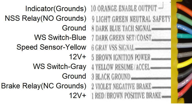
For some reason the #6 wire (main power) which is supposed to be brown was dark gray on this unit so I put this diagram together just to be sure that I had things connected properly. The right side is a picture of the actual wires on the Rostra 250-1223 that I installed. The middle is the wiring descriptions from the Rostra instructions and the left is my notes.
© 2021 Drake Smith - Please do not use or reproduce this elsewhere. Feel free to link to it though. |
|||||||||||||||||||||||||||||||||||||||||||||||||||||||||||||||||||||||||||||||||||||||||||||||||||||
![]()