![]()
|
© 2013 Drake Smith - Please do not use or reproduce this elsewhere. Feel free to link to it though. Waterproof Micro Relays
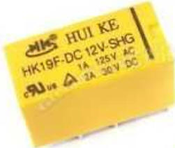
These are handy for switching LEDs and other low load applications. What I use is 12V DPDT PCB (printed circuit board) HK19F relays. These can be purchased on eBay, Amazon or from online electronics retailers like Newark or Mouser.
On some of them the "trigger" terminals are polarized, on some they aren't. You can test this (and the input/output terminals) using a 9V battery. Once I've determined the polarity of the trigger terminals and which terminals I want to use (normally open or normally closed,) I snip off the pins I won't be using and solder wires to the terminals I will be using. (The HK19F relays are not polarized.) Be sure to use soldering flux which makes the soldering much easier.
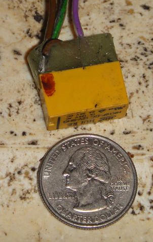
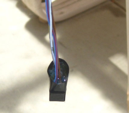
Then I wrap it in electrical tape, hang it upside down and fill the electrical tape with either five minute epoxy or JB Weld.
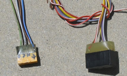
Here's a couple of examples of relays I've made. The one on the left is a HK19F two amp relay and the one on the right is an eight amp relay.
About PCB Relays: PCB relays function like automotive "Bosch" type relays. The schematic below shows the pin arrangement for a typical 12V DPDT PCB relay.
And here's a terminal pinout for a typical Bosch 5-pin relay:
Relay "Trigger" Terminals: There are two terminals labeled "-" and "+" at the top of the PCB relay shown above. When the "-" pin is connected to ground and the "+" is connected to 12V+ the relay is activated. These correspond respectively to terminals 85 and 86 on a Bosch relay. The design of these two pins can vary from relay to relay. The easiest way to determine which pin is positive and which is negative is to touch the two pins to the contacts on the top of a 9V "transistor" battery. You will hear the relay click when the polarity is correct.
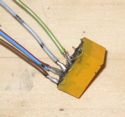
N, C & O Terminals: There are two sets of N(input), C(closed) and O(open) pins, These are respectively equivalent to the 30, 87a and 87 terminals on a Bosch relay. The three pins on each side of the relay are independent circuits. I usually just use one side. The configuration of these pin cans vary by relay but by using a continuity tester on the lower pins and triggering the relay with a 9V battery it is easy to determine which pin is which. When the relay isn't activated there should be continuity between the N terminal and the C terminal. When the relay is activated by the 9V battery there should be continuity between the N terminal and the O terminal. As you'll see on the yellow relay in the picture above, I usually label them N, C and O accordingly. On the yellow relay above, the blue wire is the 12V trigger, the brown wire is the trigger ground. They gray wire is the input to the N terminal and the green wire is output to the C terminal, making it a "normally closed" relay. On a Bosch relay the blue wire would go to the 86 terminal, the brown relay would go to the 85 terminal, the gray wire would go to the 30 terminal and the green wire would go to the 87a terminal. To make this a "normally open" relay instead, the green wire would go to the O terminal - which is the equivalent of Bosch terminal 87. © 2013 Drake Smith - Please do not use or reproduce this elsewhere. Feel free to link to it though. |
![]()