![]()
|
© 2022 Drake Smith - Please do not use or reproduce this elsewhere. Feel free to link to it though. Left Combination/Headlight Switch (And windscreen switch for late model K1100LTs) Intro: The most common failure for the left combination is a failure of some sort with the headlight switch so that the headlight does not come on or only the flash-to-pass switch works. The occurs because the current through the contacts causes heat which softens the plastic around them and they recess. This can be mitigated ahead of time by installing headlight relays to greatly reduce the current through the headlight switch contacts. Tools needed:
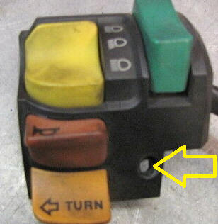
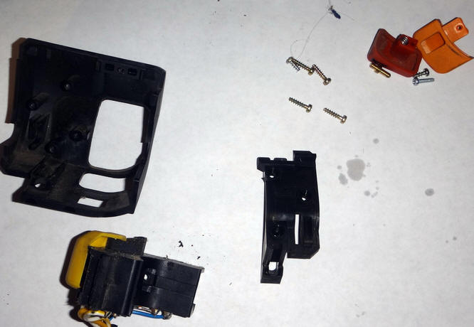
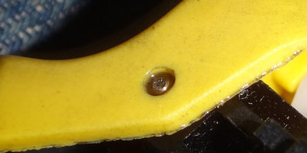
Disassembly: Since there are many small screws and parts involved, I recommend removing the left combo switch from the bike and doing this off-bike. If you choose to do it on-bike then consider doing it above a shoe box or similar to catch any small parts that may fall. 1 - Remove switch from clutch perch: There's a small Phillips screw at the bottom center that holds the switch to the clutch perch. It can be sticky so use a good screwdriver and apply lots of pressure to initially break it free. If you don't then you might strip the head of the screw.
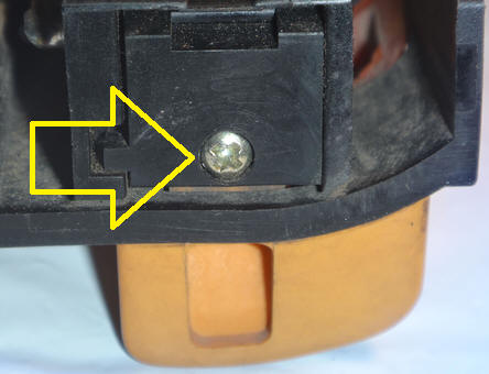
After that one screw is removed the switch lifts off of the clutch perch. You'll then need to remove the gas tank to disconnect the switch from the main wiring harness so that you can take the combination switch to the workbench. 2 - Remove the turn signal and horn buttons: The turn signal button is held on by a small Phillips screw in the back. Once this screw is removed you can wiggle the button to slide it out.
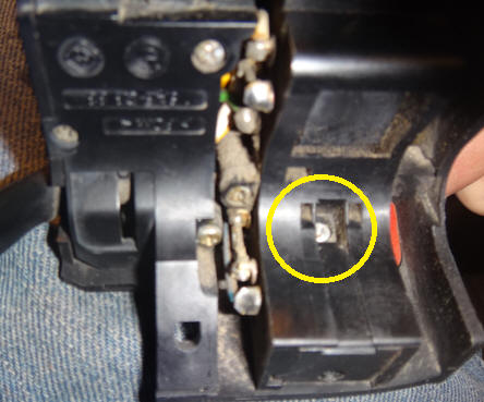
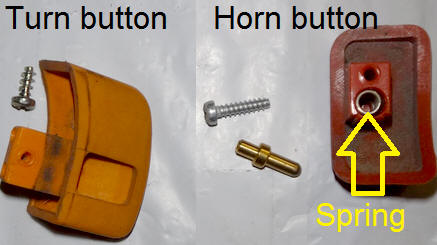
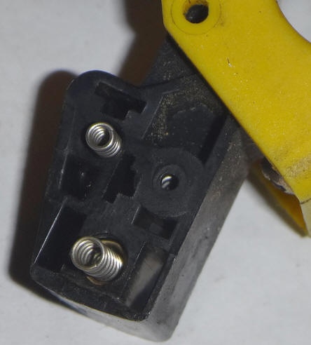
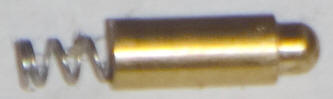
The horn button is held on by a small screw that can be accessed via a hole inside the back of the switch assembly. It's easiest to do this if you depress the horn button while removing the screw. Note the spring and pin where the horn button mounts. (When putting the horn button back on the long end of the pin goes into the switch and the short end goes into the spring in the button.)
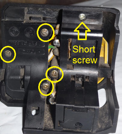
3 - Remove the 5 screws that hold the switch together: There are 2 different types of Phillips screws used. The short screw is at the top.
The switch subassembly can now be removed from the housing.
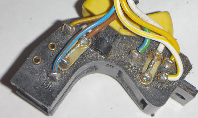
Headlight Switch: If you're taking the left switch apart then chances are you're having issues with the headlight switch. The first thing to do is inspect the solder connections and repair any issues there.
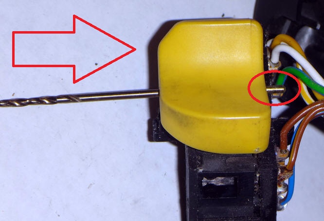
When you remove the yellow headlight button there are many small parts to lose so use caution. The headlight button rotates on a 2mm pin. Use the butt of a 2mm or 5/64" drill bit (or something similar) to push the pin out.
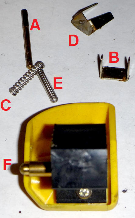
Here are the parts of the headlight button assembly:
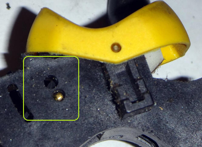
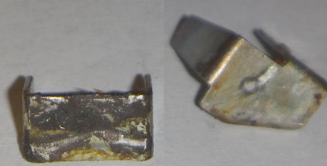
A - Axis pin B - Regular bridge: Connects low beam (yellow wire) or high beam (white wire) to headlight power (white/yellow wire) from right combination switch. (Jumped to be always on for US bikes.) C - Spring for regular bridge D - Flash bridge: Connects high beam (white wire) to load shed relay (green/blue wire) when button held in down position E - Spring for flash bridge F - High/low nub. Holds the button in regular low beam or regular high beam position. (Has a spring inside of it.) Here's where the high/low nub is on the switch:
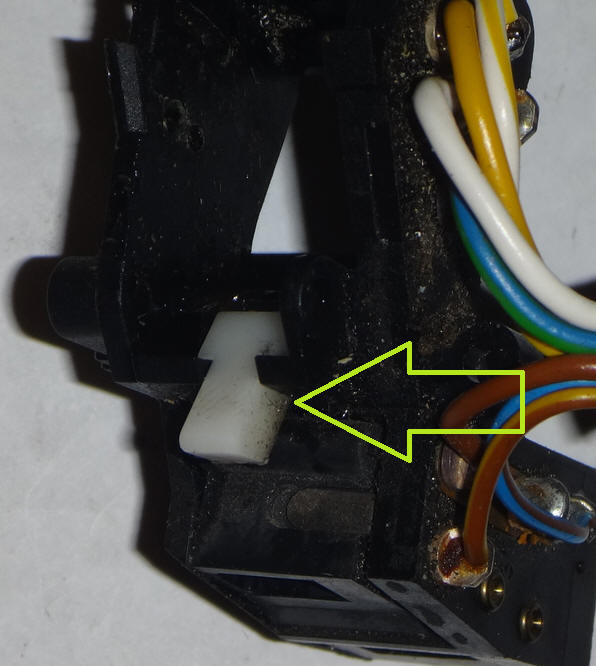
Under the button is a spring loaded rotating white lever that pushes the button back to the regular position from the flash position when it is released. Lubricate this while you have the headlight button off.
It pushes on two ribs inside the bottom of the switch button.
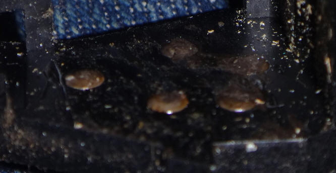
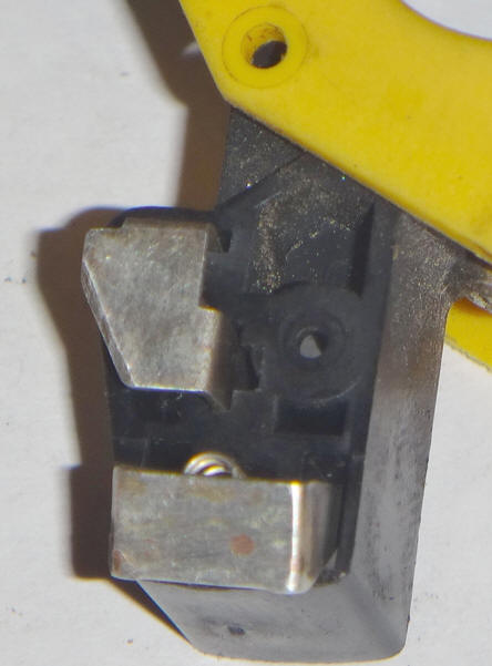
Here are the contact points inside the switch prior to cleaning:
Clean the contact points with some very fine steel wool or sandpaper. Also clean the surfaces of the bridges:
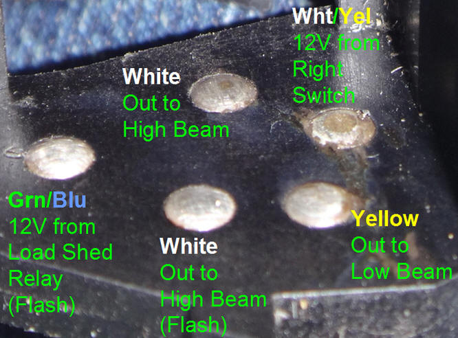
Here are the contact points cleaned up:
As you can see, the main headlight power contact (upper right) shows some wear. This is caused by the little sparks created every time you switch between the high and low beams. If this contact wears too low or the plastic around it melts so that it "sinks" then you need to replace the left combination switch. You can eliminate future wear by adding headlight relays. (Click here.) Reassembly: Install the springs and bridges:
The high/low nub (with spring) installs on the other side.
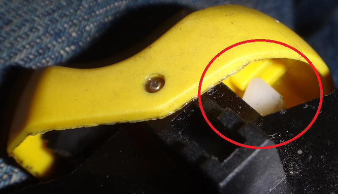
Pinch the sides of the switch so that both bridges and the nub stay in place and insert the button assembly back into the switch body. Try more or less to have the button in the up position so that it clears the sprung white lever for flashing. Holding the button in place, insert the axis pin and make sure that it is flush on both sides of the button.
Lubricate the insides of the switch and also each side where the button meets the switch body.
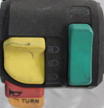
K1100LT Windscreen Switch: (Click here to skip.) Late model K1100LTs have a momentary up/down switch built into the left combo switch.
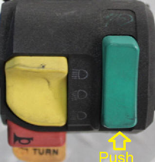
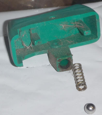
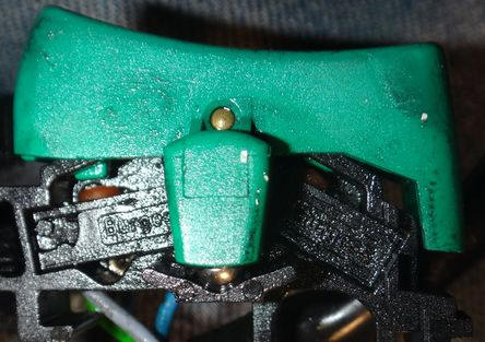
Part # 61312306058 After many miles the windscreen switch built into the left combination switch of later K1100LTs can become sticky and/or unresponsive. It is possible to take the switch apart and rehab it so that it functions "like new" again. If you have an earlier K75RT or K1100LT with the windscreen switch in the center of the handlebars then instructions on how to rehab that switch can be found at this link. To remove the windscreen switch push up on the bottom of the switch button and wiggle it out of the housing.
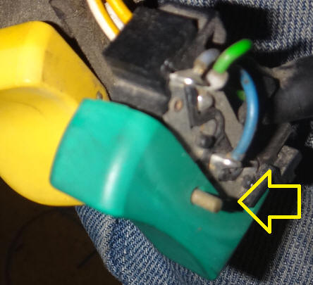
Similar to the headlight switch, the windscreen switch pivots on a pin in its center. While pushing down on the center of the button, push that pin out with the butt of a 2mmm or 5/64" drill bit or other tool. If the pivot pin has worked its way partially out like the one shown below then needle nose pliers can be used to extract the pin. Be careful at this stage as this is when a small ball bearing can escape and roll off into oblivion.
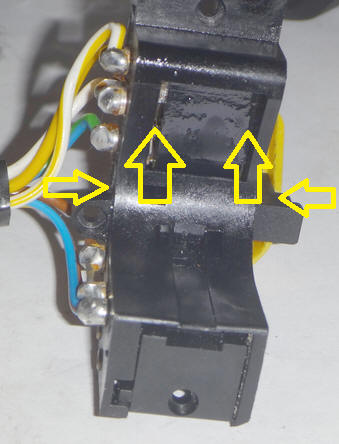
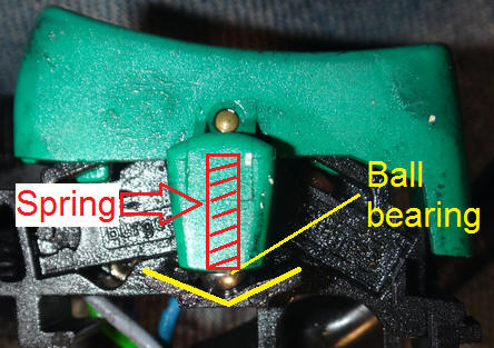
The windscreen switch re-centers itself via a spring and ball bearing on one side. The middle of the "V" shown below is the neutral switch position.
Clean out any dirt or dust that has accumulated in the "V." There are momentary micro-switches at the top and bottom of the windscreen switch. Spray some silicone lubricant into each one of those from the side.
To reassemble the windscreen switch, place the ball bearing in the bottom of the "V" and put the spring back into the switch button. Push the button back on and wiggle it around until you can push the pivot pin back through. Make sure that the pivot pin is side-to-side centered in the button.
Put the switch back into the housing and screw the back on. HORN BUTTON - Remember that the long end of the pin goes into the switch and the short end goes into the spring in the button. Do not overtighten the screw for the horn button, just get it snug. For some reason if you have that screw too tight then the button does not move as freely as it should. © 2022 Drake Smith - Please do not use or reproduce this elsewhere. Feel free to link to it though. |
![]()