![]()
|
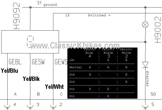
© 2013 Drake Smith - Please do not use or reproduce this elsewhere. Feel free to link to it though. Gear Position Indicator (GPI) The LCD digital gear number display in the right side of the tachometer faceplate is known as the gear position indicator. (GPI) It is driven by a rotating switch forward of the swing arm on the back of the transmission. It has a ground for input and three output wires: yellow/blue, yellow/black and yellow/white. The GPI circuit board inside of the instrument cluster determines/displays what gear you're in based upon which combination of the three yellow/other color wires is grounded. (See graphic below.) When all three of the yellow/other color wires are grounded then the GPI circuitry knows that the transmission is in neutral. When in neutral, the GPI circuitry displays zero and sends 12V to illuminate the neutral light in the instrument cluster and also sends 12V to the starter button in the right combination switch via a black/green wire.
The connector for the GPI switch is located under the right side cover. It has a four wire connector with the following wires:
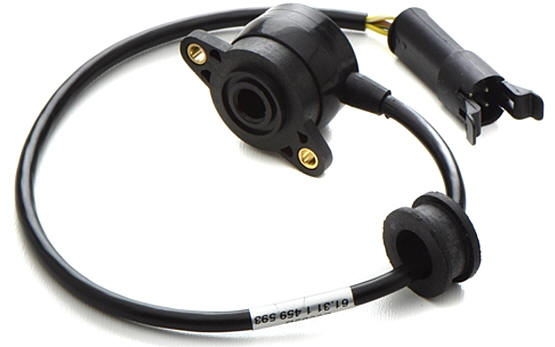
The GPI switch is BMW part 61311459593 and looks like this: (except for early K100s where the connector will be white, not black)
Living where it does on the back of the transmission, the GPI switch has a hard life and is prone to eventual degradation and failure. This is often the reason why the gear number displayed in the instrument cluster may be wonky after riding in the rain or washing your bike. When its housing degrades water leaks in and randomly grounds the wires to cause wonky LCD readings.
If your GPI is acting up then the first thing to do is to diagnose whether your problem is caused by the GPI switch on the transmission or the GPI circuit board in the instrument cluster. The connector from the switch to the instrument cluster is located under the right side/battery cover. It has a brown wire and three yellow/other color(blue-black-white) wires. Testing The GPI Switch Note that if your gear indicator goes wonky after washing the bike or riding in heavy rain then that's usually an indication that the switch is the problem because water is getting inside of it and causing inadvertent short circuits. Using a multimeter/ohmmeter on the connector to the switch, test continuity between the ground (brown) wire and the other wires as shown below. A properly working GPI switch will yield the following results: (X=Continuity)
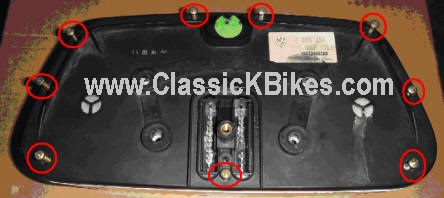
Place the bike on the center stand and rock the rear wheel back and forth to make shifting between gears easier. If you determine that the switch is the problem then the final drive and swing arm need to be removed in order to access/replace the switch. (Given the work involved I think it makes sense to buy a new switch (Part 61311459593) if you can afford it. A used switch might not last very long.) Testing The LCD Indicator In The Instrument Cluster On the connector that goes to the instrument cluster, shorting the yellow/other color wires to ground per the table above should indicate the gears as shown. (The ignition needs to be turned on when you do this.) No Neutral - Bike Won't Start If the GPI does not recognize neutral and illuminate the neutral lamp then you can alternately get power to the start button by pulling in the clutch lever. Replacing the GPI Circuit Board If you determine that the GPI circuit board in the instrument cluster is the problem then this can be replaced as a separate part (Part 62111459238) without having to replace the entire instrument cluster assembly. To replace the GPI circuit board: 1 - Remove the instrument cluster from the bike. (Click here for instructions on how to remove the instrument cluster.) 2 - Place the cluster upside down on a towel/rag to protect the front of it from scratching. 3 - Remove the nine (seven on 85 and earlier bikes) Philips screws around the perimeter of the back of the instrument cluster to remove the backplate.
4 - Once the backplate is removed, remove the six Philips screws that hold the instruments inside the instrument cluster housing. There is one screw on each side and four at the bottom center.
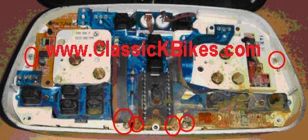
5 - Remove the two recessed screws from the back of the tachometer. These screws are what hold the GPI circuit board in place.
6 - Pull the trip odometer knob out to the extent that it's spring will let you and carefully shake the instruments out of the housing. There's a notch in the faceplate it will pass through. (Be very careful from here on out as the speedo and tach needles are very fragile will bend if you look at them crossways.)
7 - From the side, remove the white plastic spacer that was held in place by those two screws.
8 - It's a tight fit but you can then carefully pry the pins of the GPI circuit board off and slide it out from the top.
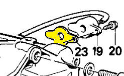
9 - Reassembly is the reverse of disassembly. Replacing the GPI Switch To replace the GPI switch (part 61311459593) you need to remove the aft portion of the drive train in order to get the swing arm off. You should also consider replacing the gasket - part 23111464014.
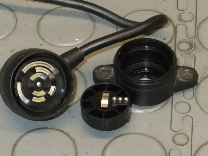
Repair the GPI Switch The GPI switch costs well over $100 so you might want to attempt to repair it. Depending upon how degraded the switch is it may be possible to repair by merely resealing it. If you attempt to disassemble it then do that in a shoe box or plastic bag as there are tiny springs and pins that can be easily lost. Here's what the inside of the GPI switch looks like:
© 2013 Drake Smith - Please do not use or reproduce this elsewhere. Feel free to link to it though. |
![]()