![]()
|
© 2024 Drake Smith - Please do not use or reproduce this elsewhere. Feel free to link to it though. Speedometer Calibration Intro: K bike speedometers usually run about 10% fast from the factory. However, it is fairly easy to recalibrate one yourself. This page shows several methods to accomplish this. Updated for 2024: After measuring the output frequencies of both the Karamba and K-DIAG Windows apps and discovering that they are erroneous I no longer recommend using either tool for speedometer calibration. (See here: Motobrick) There may also be slight differences unique to individual speedometers so I now prefer a very simple method that ensures better results using Windows or Android frequency generator for speedometer calibration. (Method 2 below.) 1) Soldering Iron Method Many soldering irons emit a magnetic field at a frequency of 60 Hz. (In the US. It's 50 Hz in some other countries.) This is the frequency of normal household 120V alternating current. If the magnetic field put out by your soldering iron is strong enough (some are, some aren't) then you can use that field to send a 60 Hz signal through the speed sensor of a K bike final drive in order to calibrate the speedometer. Determine V1: Remove the speed sensor from the final drive and wipe it clean. Turn the ignition switch on, plug in the soldering iron in and hold it close to the speed sensor. Your speedometer needle should now read somewhere in the middle to high 40s MPH. While doing this, make sure that your eyes are about where they are when you are riding. Write down or remember that speedometer reading as V1. Determine V2: Re-install the speed sensor and go far a ride with a GPS or phone with GPS/speed app. Ride so that the speedometer reading is a constant V1. Observe the GPS speed. That speed is V2, what a calibrated speedometer should read when the speed sensor is generating 60 Hz.
Remove
instrument cluster: Remove the four 5mm Allen
bolts on the back of the instrument cluster that hold the
instrument cluster in it's bracket. Then, depending on the
model year of your K bike, there is either a Phillips screw
or 3mm Allen bolt that holds the wiring harness connector to
the back of the cluster. Remove instrument cluster internals: There are six screws that hold the internals in the instrument cluster - four at the middle bottom and one on each side. Remove those six screws, turn the cluster over and carefully shake the internals out - pull out the trip odometer knob as far as it will go while doing this - there's a notch in the side of the speedometer face plate which lets it pass by the trip odometer rod.
Warning: Be very careful
with the instruments once removed. Try not to get
fingerprints on the face plates and be very careful with the
speed and tach needles - they may fall off or bend if you look at
them crossways.
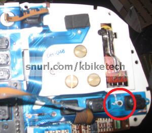
Locate calibration potentiometer: The arrow below shows location of the potentiometer that controls speedometer calibration.
Adjust
the potentiometer: Use a small screwdriver or
knife tip to turn the potentiometer counterclockwise
about 45 degrees which should get the calibration fairly
close.
2) Frequency Generation Ride Method (Best)
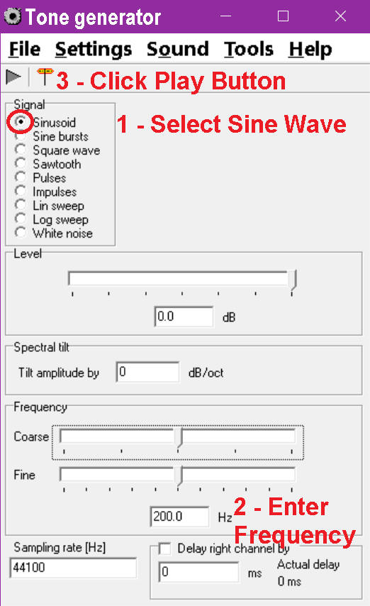
An alternative to the soldering iron method is to use a frequency generator. Since using a frequency generator allows calibration at a higher speed than the soldering iron method it should give better results. Windows - I use a frequency generator freeware app. Download here: tone.exe
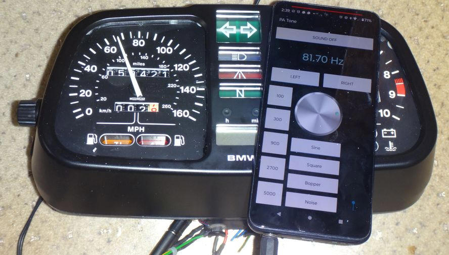
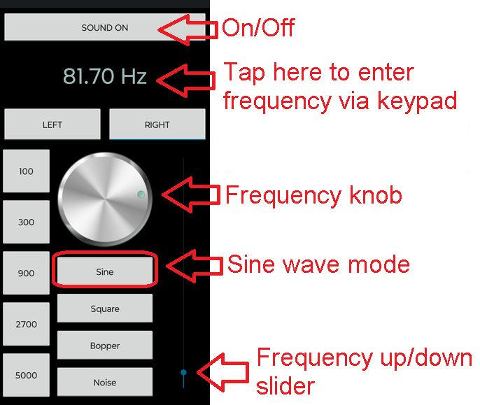
Android Phone - (Only for phones with a headphone jack.) I use Frequency Sound Generator by LuxDeLux (Play Store link) because it is free and allows the user to type in two digit decimal frequencies.
Headphone Jack Connection - You'll need a 1/8"(3mm) stereo headphone plug with two wires attached, one wire is ground and the other wire should be attached to either the right or left channel. (But not both.) You can either DIY it with a plug like this or buy a prewired plug like this.
Connect To Speedometer - The connector for the speed sensor is under the right side cover. It has two wires, yellow and brown. There are two types of connectors that were used:
1992 and earlier Ks - You can use two 1/8" female blade connectors to connect your wired audio plug to the main wiring harness connector for the speed sensor. 1993 and later Ks - You can use Posi-Taps to connect your wired audio plug to the main wiring harness connector for the speed sensor. It's optional but once you have the above wiring ready to go you may want to hook your laptop or phone up and test to see if a frequency of 80 Hz works on your speedometer. Note that the ignition key needs to be turned on so that the speedometer has power. Make sure that the frequency generator is in Sine Wave mode. Remove the speed sensor from the final drive, wipe it clean and then reinstall it. Determine V1 and V2: Take your K for a ride with a GPS or phone with a GPS/speed app. Riding at a constant fairly high speed (60-70 MPH or 100-110 kph), make a mental note of both the speedometer speed, V1, and the GPS speed, V2. If you plan to adjust the calibration on the workbench then also remember the position and viewing angle of your eyes relative to the instrument cluster. Ride home. Determine Frequency for V1: Connect your laptop or phone to the speed sensor connector and, via trial and error, determine what frequency causes the speedometer to read V1 when seated in your normal riding position. Starting at 80 Hz should get you in the right neighborhood. Once you determine the frequency for V1, write it down or remember it as FC.
Remove
instrument cluster: Remove the four 5mm Allen
bolts on the back of the instrument cluster that hold the
instrument cluster in it's bracket. Then, depending on the
model year of your K bike, there is either a Phillips screw
or 3mm Allen bolt that holds the wiring harness connector to
the back of the cluster. Remove instrument cluster internals: There are six screws that hold the internals in the instrument cluster - four at the middle bottom and one on each side. Remove those six screws, turn the cluster over and carefully shake the internals out - pull out the trip odometer knob as far as it will go while doing this - there's a notch in the side of the speedometer face plate which lets it pass by the trip odometer rod.
Warning: Be very careful
with the instruments once removed. Try not to get
fingerprints on the face plates and be very careful with the
speed and tach needles - they may fall off or bend if you look at
them crossways.
Locate calibration potentiometer: The arrow below shows location of the potentiometer that controls speedometer calibration.
Adjust the potentiometer: Use a small screwdriver or knife tip to turn the potentiometer counterclockwise about 45 degrees which should get the calibration fairly close. Then fine tune the angle of the potentiometer until the frequency FC noted above causes the speedometer to read V2 at your usual viewing angle. Calibration is complete. Warning: If, when testing, you misalign the connector pins on the instrument cluster when hooking it up you can fry your $75 Bulb Monitor Unit in the relay box. Reassemble: Reassembly is the reverse of disassembly. Remember to pull the trip odometer knob out while sliding the internals back into the housing.
3) Frequency Generation Workbench Method As noted above, the frequencies produced by both Karamba and K-Diag are a bit off so I don't recommend using them. If you want to skip the methods above and just calibrate using frequencies then the following PDF table shows the correctly calculated frequencies for various rear tire sizes at various speeds. Link: K.Bike.Speedo.Cal.pdf
Best Method: The best method is Method 2 because it will be the most accurate for your speedometer on your K at speed.
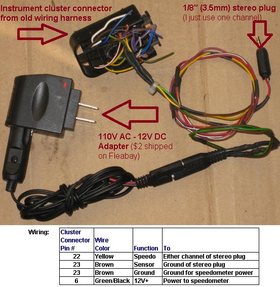
Since I had a spare instrument cluster connector I fabricated this wiring harness for calibrating K bike speedometers.
© 2024 Drake Smith - Please do not use or reproduce this elsewhere. Feel free to link to it though. |
![]()