![]()
|
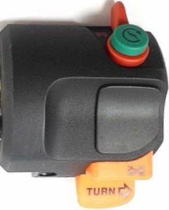
© 2022 Drake Smith - Please do not use or reproduce this elsewhere. Feel free to link to it though. Right Combination Switch There are two versions of the right combo switch, one version for the "always on" lighting of US K bikes and a "Euro" version used on K bikes sold in other countries. The Euro switch allows a rider to control the parking light in the headlight, the tail light and the headlight. (The BMW parts fiche refers to the US switch as "continuous light.")
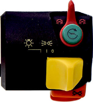
Euro switch positions:
The switches are identical for 2 valve and 4 valve K bikes. The wiring colors are the same. The only difference is the connector.
Wiring:
Some police model K bikes have more than one connector to the Euro switch so that the light switch could be used for special police auxiliary lighting. NOTE: The headlight is supposed to go out when starting a K bike. The load shed relay turns off the headlight and some other circuits so that there is more electrical power available for starting.
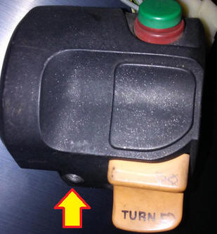
Disassembly & Repair: The first step is to remove the switch from the throttle perch. Just remove the Phillips head screw at the bottom middle of the switch and slide the switch upwards to remove it.
IMPORTANT: Many times the last time that screw was touched was when it was installed at the factory so the threads might be sticky. Therefore I recommend using a quality Phillips screwdriver with a good head and lots of direct pressure on the screwdriver to initially break the threads free. If you don't do this then you run the risk of stripping the head of that screw. There are tiny screws and springs to lose so it's a good idea to pull the tank back, disconnect the combo switch and service the switch on a workbench. At the very least, if you plan to do this at the bike then do it above a shoebox or similar in order to catch any dropped parts.
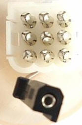
START/KILL SWITCH: With the start button pointing downwards, rotate the E-clip that holds the start/kill switch assembly so that you can pop off the E-clip.
You can then push the start/kill switch out.
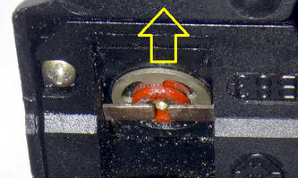
The kill switch is comprised of the switch body, a metal contact ring and two tiny springs. The tiny springs fit in these holes under the contact ring.
If there is corrosion on the contact ring then clean it with some fine steel wool or sandpaper. Also check/clean the corresponding contacts in the combo switch body.
REPLACEMENT START BUTTON: There's a guy in Spain who sells replacement start buttons:
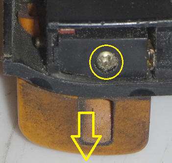
TURN SIGNAL BUTTON: Once the screw for the turn signal button has been removed you can wiggle the button out from the bottom.
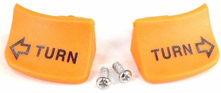
If your turn signal button is broken then you can buy a replacement pair of turn signal buttons (left and right) from BMW. The part number for the pair is 61319062462. These are the only combo switch buttons that BMW sells replacements for.
CANCEL BUTTON: The cancel button is held on by this screw. I find it easiest to undo this screw with the cancel button depressed.
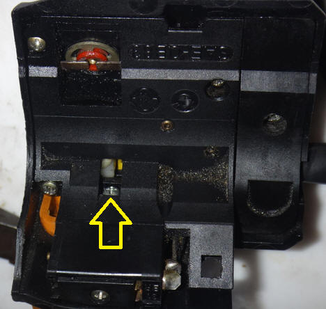
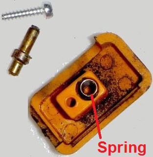
Inside of the cancel button are a small rod and spring. When reinstalling the cancel button the long end of the rod goes into the switch and the short end goes into the spring in the button.
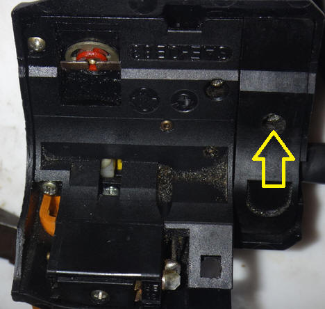
HEADLIGHT SWITCH: This somewhat tricky to put back together so I do not recommend any further disassembly unless you are having issues with the headlight switch. There is a tiny ball bearing in the headlight switch that is very easy to lose. Even if you are doing this at the workbench I recommend doing any further disassembly over a shoebox in order to keep from losing that ball bearing. You've been warned. There are four screws that hold the switch assembly together. First remove this screw to take off what I refer to as the side piece.
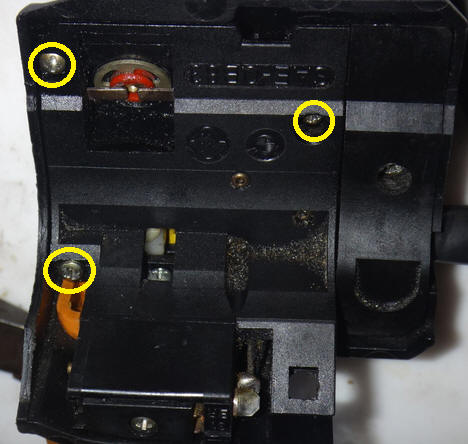
Now remove the three remaining screws that hold the switch together. (Being careful not to lose the tiny ball bearing when it drops out of the switch.) Note that the screw up near the start/kill switch is shorter than the other two screws.
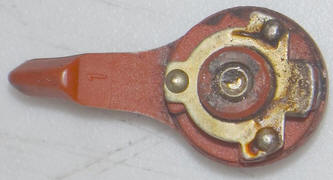
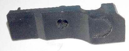
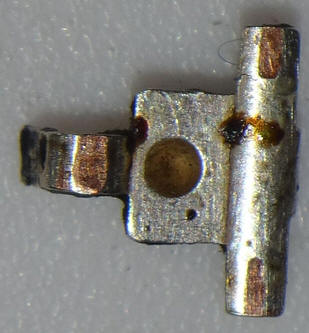
Here is what the switch housing half looks like once disassembled. This is the part that slides when the yellow button is moved.
You may notice that the white nylon part that attaches to the yellow button seems a little wobbly. Do not worry about that. It is normal for it to be like that when the switch is disassembled. The screw can be removed to separate the white nylon part from the yellow switch button but there should be no need to do that. The contact plate can be lifted off and cleaned with some fine steel wool or sandpaper.
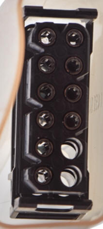
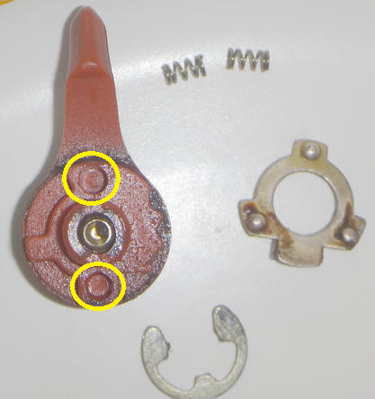
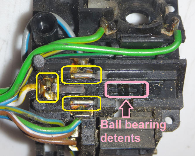
Here is what the other half looks like with the contact points shown in the yellow boxes. Clean these contacts too.
Lubricate everything with spray silicone before reassembly.
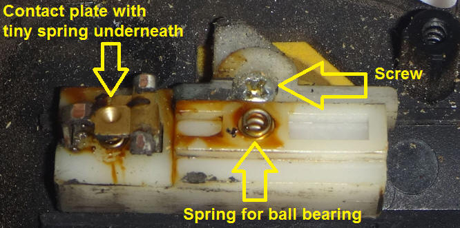
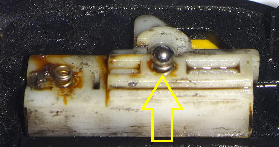
Now comes the tricky part - reassembly. It make take a few tries to get it right but with a little patience you'll get there. This should be done over a shoebox or similar since the tiny ball bearing may try to escape. Hold the switch body so that the white nylon slide is level. Place the ball bearing in its spring.
Though not shown in the picture above, the contact plate should be reinstalled over the spring on the left. Then lower the other half straight down trying not to disturb the ball bearing. Once you have both halves back together hold them firmly together while sliding the button to be sure things are as they should be. If the button slides correctly then keep holding the switch tightly together as you install the three screws. Once you have the three screws installed test the sliding yellow button again just to be sure that everything is working correctly. Then reinstall the side piece, start/kill switch, cancel button and turn signal button.
© 2022 Drake Smith - Please do not use or reproduce this elsewhere. Feel free to link to it though. |
![]()